Some time ago, I got my son his first phone, obstensibly for coordinating school pickups between family and friends. I deliberately went down-market and got the most budget Android smart-phone I could… some Alcatel budget model. Something that would still allow for a small collection of useful apps, but would not invite a lot of gaming potential. The hardest problem was trying to find a phone case; any phone case.
My options at the time were limited to a universal case… you know, the type of folio case that turns a relatively svelte phone into something the size of a Gideon’s Bible, that you can add cards to, attempts to house a range of phone sizes with elastic straps and completely covers the rear camera. So I bought it.
Fast forward to present day and we’ve barely got three elastic straps still holding on, the cards are so loose they fall out, and there is now a large hole I hacked with a pocket-knife while on holiday so the camera could be used. But at least the phone remains undamaged, so … hurray for the case, I suppose.
I do now have a 3D printer, and have done a few interesting things with OpenSCAD, so I thought I’d have a crack at designing and printing a custom phone case.
Did I scour the internet to see if anyone had done this before? No, of course not, where would be the fun and learning in that? I did however think that making the case in TPU would be an interesting experience. TPU is a type of thermoplastic elastomer… like what your plastic sandals that want to be Crocs are made of. Turns out you can 3D Print with that, so I’ve ordered a small 200g spool of anonymous TPU 95A filament… and it should be here in a few days.
In the meantime, I can work with the PLA I have to hand… probably the only project that I’ve done where lime green is actually a fairly good colour choice.
Don’t forget the basics of a design process: start with sketches and brainstorming to critically evaluate ideas and make changes when it’s easiest to do so.
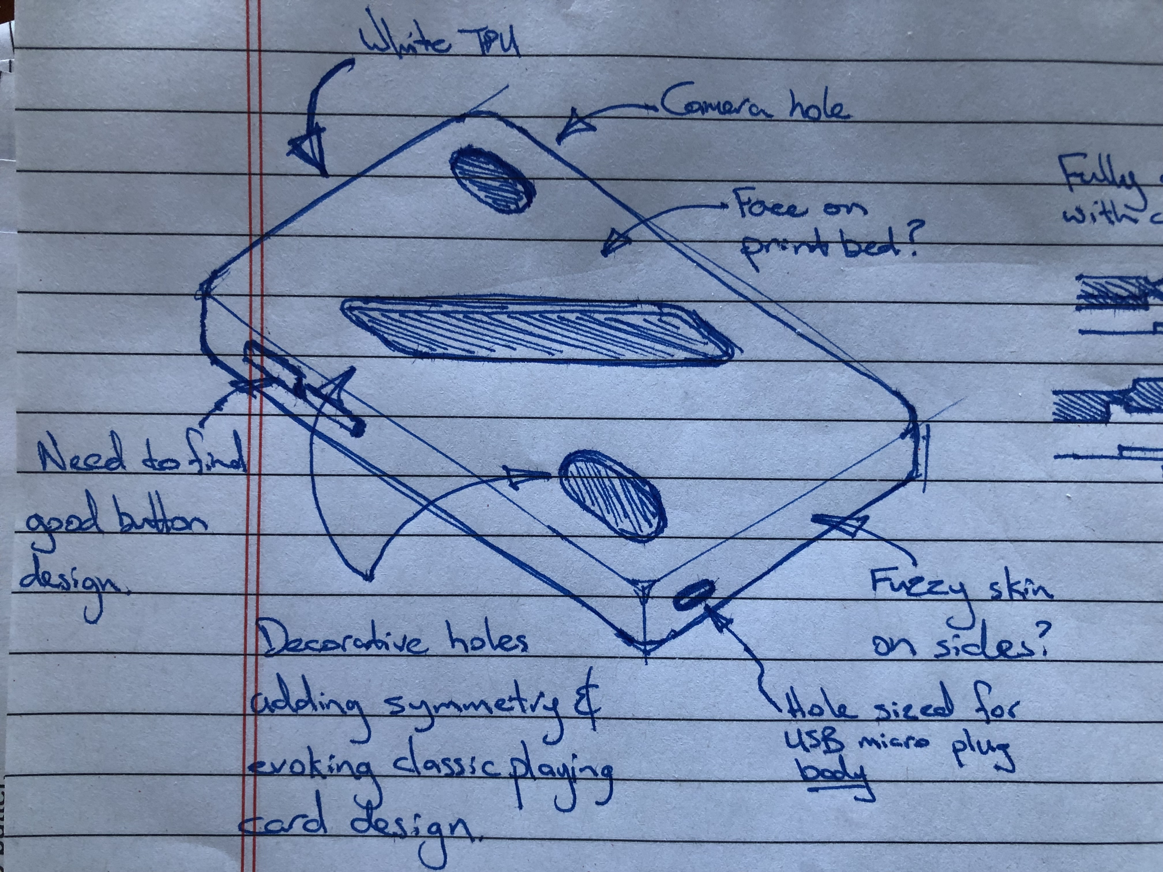
An isometric sketch of a phone case, showing some early ideas about decoration, material selection, and exploring the handling of buttons and holes.
To make your own phone case, you will need:
- Vernier Calipers (highly recommended so you can measure to 0.1mm). If you can, I suggest getting a manual one with larger metal body, it will last better and can take different types of measurements with a larger dimention than a cheap digital electric one. I’ve got my Dad’s old pair, and they still work very well.
- The phone you want to make a case for; but you only need it to take measurements and photos.
- Photos of said phone from each angle; good for reference later if the phone is for someone else.
- OpenSCAD
- and of course a 3D Printer and slicing software. I used Prusa Slicer to go with my Prusa MK3S+ printer… nothing fancy in terms of hardware by today’s standards.
Measuring
Grab the phone, open a new OpenSCAD document, and start recording the various measurements. Thorough naming will help here. I referenced all my measurements from the (extrapolated) corners of the phone’s body. Try to be precise; using calipers will get you 0.1mm precision easily, and you’ll want that to help ensure a good fit, considering that a print layer is often 0.2mm with a nozzle-width of 0.4mm.
Here’s an example of what I recorded:
body_thickness = 10;
body_width = 71.8;
body_length = 146.2;
body_corner_radius_xy = 7;
glass_width = 67.8;
glass_length = 142.4;
//glass_inset = 2; // TODO: validate // TPU
glass_inset = 0.5; // TODO: validate // PLA

// Side of phone appears to have a radius of about 6mm, tangent
// with the rear face, and wrapping around.
side_profile_radius= 6;

// Rear camera is on the right (when viewed from front) on the rear face
camera_slot_top_offset = 15;
camera_slot_right_offset = 15;
camera_slot_length = 10;
camera_slot_radius = 9.5 / 2; // likely will still need bevel

button_slot_radius = 2;
button_slot_front_offset = 4.5;

//Camera button is on the left side
camera_button_slot_top_offset = 51.5;
camera_button_slot_length = 9.6;

...
Notice how each variable describes the particular component it relates to, the type of thing being measured (eg ‘slot’) and its reference point (eg. offset from the front face, top, etc.)
OpenSCAD is unitless, so it’s only by convention that I’ve specified my units in millimeters.
With regard to slots, since slots are essentially rectangles with a semi-circle on each end, I tried to measure them from the radius of each end. That lost me some precision, but makes it easier to adjust the radius later, and I small make button_slot_radius smaller next time. You could measure each button precisely with the calipers and then do some simple math to precisely work out the centers, but I didn’t feel a need to go that far. The case (when printed in TPU) would have to accommodate some stretch anyway, which would benefit from a bit of a gap between button and case.
Modelling
There are surprisingly few primitives required, but the body of the phone is more rounded on the bottom, which brings with it a bit of a fun challenge.
The essential premise is first model the phone and the cutouts the buttons will need, and subtract all that from the case, which is easily calculated from the phone.
Phone Body
- A wafer-thin
cube(cuboid) runs between the internal corners of the body. minkowskithatcubewith a smallsphere… that produces a slab with rounded corners and edges.- Use
intersectionwith a largercubeto slice of what will be the front of the phone. This is how this particular phone gets its side-profile, the center of the side profile’s arc sits above the centerline.
module phone_body() {
    // Phone is positioned so resulting front face is 0z, on the xy plane
    // and the left side of the body is flush with 0x and the bottom (end) side
    // of the body is flush with 0y

    intersection() {
        minkowski() {
            translate([
                    side_profile_radius,
                    side_profile_radius,
                    -body_thickness + side_profile_radius])
                cube([
                    body_width - 2*side_profile_radius,
                    body_length - 2*side_profile_radius,
                    0.001]);
            sphere(r=side_profile_radius);
        }
        translate([0,0,-body_thickness])
            cube([body_width,body_length,body_thickness]);
    }
}
Here’s a separate model that I’ve created to show how the different primitives are used to create the basic phone body.
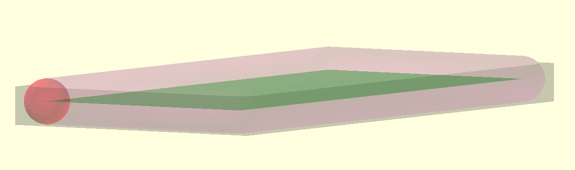
A view of the phone_body_exploration model, showing how a sheet-thin cuboid (in green) and a small sphere (in red) are used by the minkowski operation to create the rounded slab (in purple). Finally, we intersect that with a box (in gray) to produce a reasonable facsimile of the phone’s basic body.
The phone body will be used as a ’negative’ to form the inside of the case. We shall next create other negatives to cut-out allowances for where the buttons and plugs need to be exposed.
Cutouts
This is where cylinder and hull work together to create the slots. You could get a bit more fancy and create a slot module, but I found it easiest in this case to copy/paste/edit, because to do otherwise felt a bit like premature optimisation.
Each cylinder will have a beginning radius that is slightly smaller than the button/feature it surrounds, and an ending radius that flares out a little wider so that the hole has a pleasing slope to it. Each of these slot ’negatives’ typically extend out to a nominal 5mm (punching through the case) and flare out 1.5mm.
Don’t forget features like camera light sensors, microphone holes, headphone jacks, and leave enough space for the plastic moulding around things like the USB connector and microphone jack so you don’t inadvertently prevent the plug from fully engaging.
module rear_camera_slot() {
    hull() {
        translate([
                body_width - camera_slot_right_offset,
                body_length - camera_slot_top_offset,
                -body_thickness+0.1])
            rotate([180,0,0])
            cylinder(h=through, r1=camera_slot_radius, r2=camera_slot_radius+flare);
        translate([
                body_width - camera_slot_right_offset,
                body_length - camera_slot_top_offset - camera_slot_length,
                -body_thickness+0.1])
            rotate([180,0,0])
            cylinder(h=through, r1=camera_slot_radius, r2=camera_slot_radius+flare);
    }
}
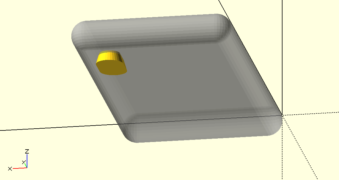
The cutout (shown in yellow) for the rear camera, with the phone body shown faded for reference. Viewed from below the Z axes.
Add your decorative cutouts here too. In this design, I employed some rotational symmetry and added a fairly simple diagonal slash to evoke a classic playing card design. Expect to have some productive play with this… have some fun with the math.
Case
Now you can take your phone body module, minkowski that with a small sphere that has a radius according to the thickness of the case you want. From that, difference away the phone body and all the other cutouts.
There you go, as easy as 1, 2, minkowski!
module case_blank() {
    minkowski() {
        phone_body();
        sphere(d=case_wall_thickness);
    }
}

difference() {
    case_blank();
    phone_body();
    rear_camera_slot();
    camera_button_slot();
    volume_button_slot();
    sleep_button_slot();
    usb_slot();
    mic_hole();
    headphone_hole();
    glass();
    case_decorative_cutouts();
}
I did allow for a greater wrap-around for the TPU version to allow for bit more of a stretch fit, so modelled a cut-out for the glass. Not needed for the PLA version, which is what’s shown in the screenshots, as the case has a very pleasing snap-on fit.
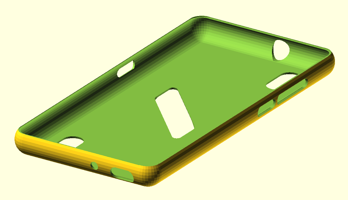
The end result of the model, rendered and ready to export as a 3MF file and send to the slicer.
Slicing
But before I printed it, I wanted to add some texture to the sides with PrusaSlicer’s Fuzzy Skin feature. You’ll need to have ‘Expert mode’ selected to see the Fuzzy Skin options. Other slicers have this too; it’s fairly new in PrusaSlicer, so you might need to update your software.
To use Fuzzy Skin, you’ll want to use the ‘Paint on Fuzzy Skin’ feature. Use the ‘Smart fill’ tool type, not the brush, and experiment with the ‘Smart fill angle’. Use this to first select all of the outside model surfaces, then deselect the faces that you don’t want to have the fuzzy texture. You’ll really need to play with the smart fill angle to get deselection working nicely; there was only a small range of angles which could allow me to select the entire layer of faces at once; but otherwise painting (to deselect) also worked well.
You’ll notice that that the ‘Paint-on fuzzy skin’ tool doesn’t expose the fuzzy parameters, such as how fuzzy you want it. To do that, you’ll need to add the ‘Fuzzy Skin’ setting to your layer, which you can do from the layer selecter. Just set the Fuzzy Skin mode to ‘None’, and then change the Fuzzy Skin Thickness to be what you like; I went with 0.2mm.
Part of my idea of trying fuzzy skin was to give some shock absorbence as well as grip… I expect it would need a higher fuzzy skin thickness to be useful for shock absorbance, but I toned it down because the case is only a couple of perimeters, and I didn’t want to invite layer separation when putting the case on. 0.2mm certainly looks good in the light.
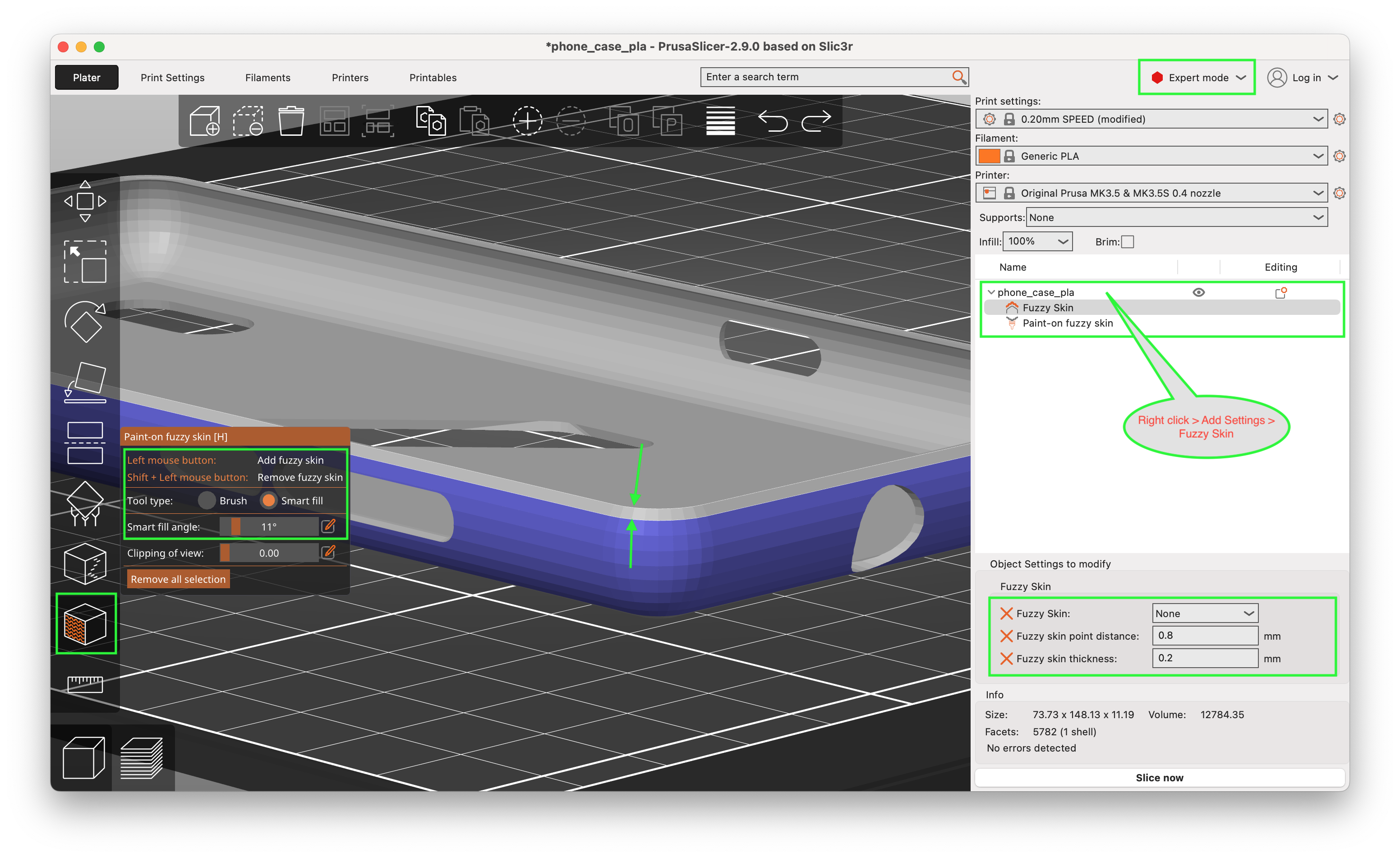
Using the paint-on fuzzy-skin tool in smart-fill mode with a smaller smart fill angle allowing me to deselect the top rim of faces. Also shows the ‘Fuzzy Skin’ settings that will apply also to the ‘Paint-on fuzzy skin’
I printed this without any supports, oriented so the largest face (the outside rear of the phone) was on the print bed. Worked surprisingly well; didn’t have any problems with the overhangs of the slots. Used print setting Speed 0.2mm layer height, with a generic PLA filament.
The only thing I was a bit disappointed with was the first few layers immediately after the base layer because of the steep overhang from the curvature. But I can live with that; can sand it if needed, plus PLA paints well. I suppose you could also print it up the other way, which would invite other kinds of detailing, but you’d want to add a brim in that case plus supports on base-plate.
Worth it?
Totally. I was very pleasantly surprised how well it worked in PLA first time. The lime green filament really works well, and the fuzzy skin texture really plays well with the light.
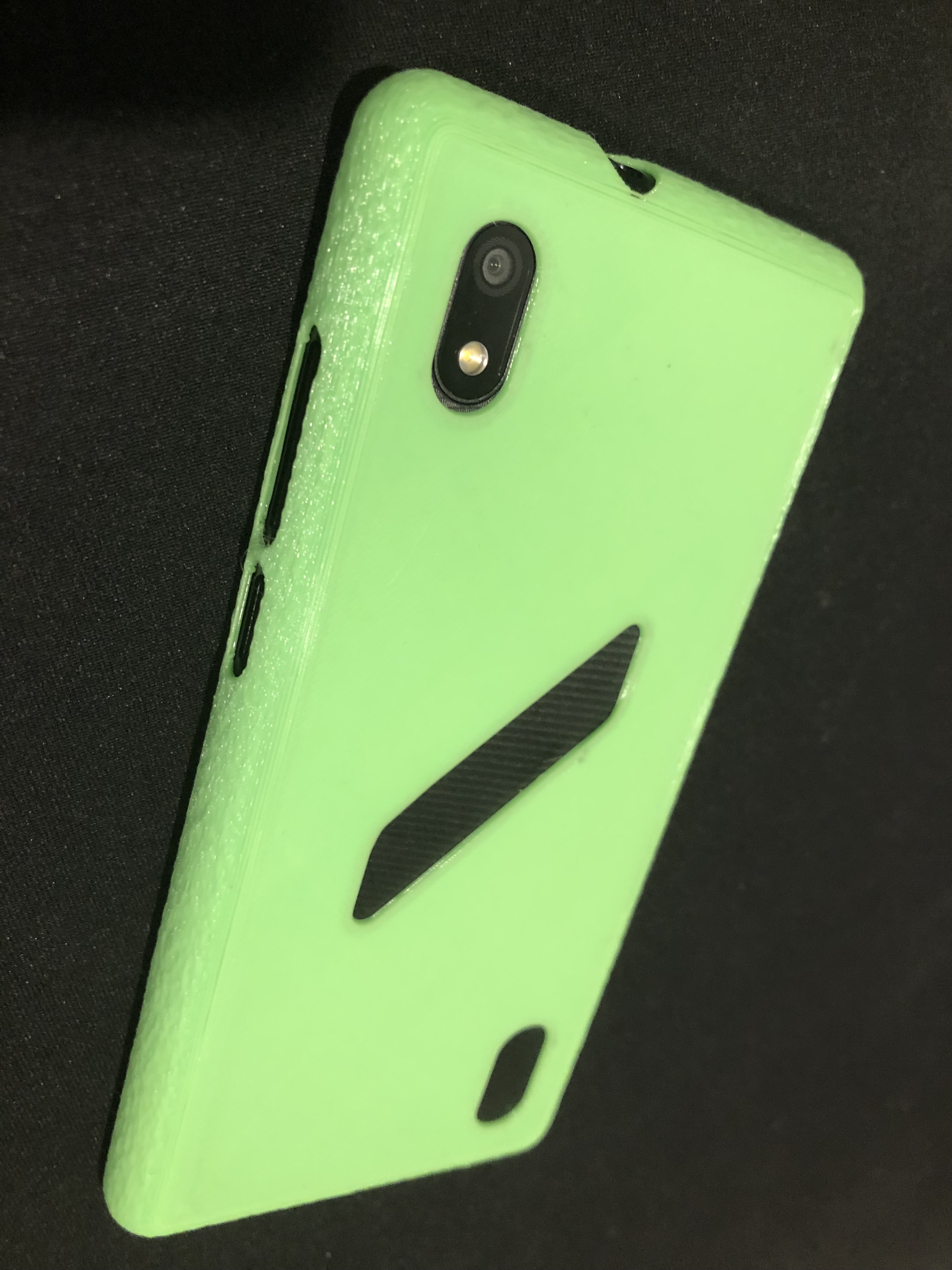
Using PLA, the result came out surprisingly well first time.
Best of all, my son has been giving me some very good feedback about how much he likes it… he’s even stopped bugging me for a new phone.
Only possible regret is that I probably didn’t need to buy the TPU; but that’s an adventure for another day.
Other Ideas for Decoration
I’ve had great success at sanding and painting PLA, but there’s loads of things you might try.
- PLA is easy to sand and paint, and a great way to explore basic painting techniques. You could include some glow-in-the-dark powder, or use a moulding medium to build up something with more relief… so have fun with it. Just be sure to apply a good hard sealer (eg. ModPodge) and let it cure.
- You could also use a 3D pen to add some relief.
- Use carving chisels to hand-work some designs into the case.
- Sanded and primed, you could use it as a base for any artistic endeavour… decoupage, impress a texture into clay-polymer, pouring paints, spray paint art, practice some Bob Ross.
The key will be to use an appropriate sealer to protect it from the elements (not just sweaty hands, but also warm sweaty male pockets with storms of pocket lint and the occassional basking in the sun)
Some more experimental ideas:
- Experiment using a technique such as Kalrosing to tattoo a design into the plastic. Use ModPodge or similar to seal it.
- Remember in school when you made a picture by adding splotches of different colours in crayon, then covered the entire sheet with a thick layer of black, then etched your design into the black to expose the colour below? Yeah, try that, but with paint. Make sure the underlying colour has enough time to dry before adding the top (black) layer, then etch off using a suitably soft stylus, perhaps a skewer? Let dry, seal and cure.