My elderly parents-in-law make regular use of a magnifying glass to help them read. Alas, mum’s preferred magnifying glass had a frame that was more than a little broken, and the lens was only held in place with a copious amount of tape. I did buy them a replacement, but could not find one on the local market that was quite right. So I thought this would be a good opportunity to design and print a new frame. A good opportunity for some fun with OpenSCAD.
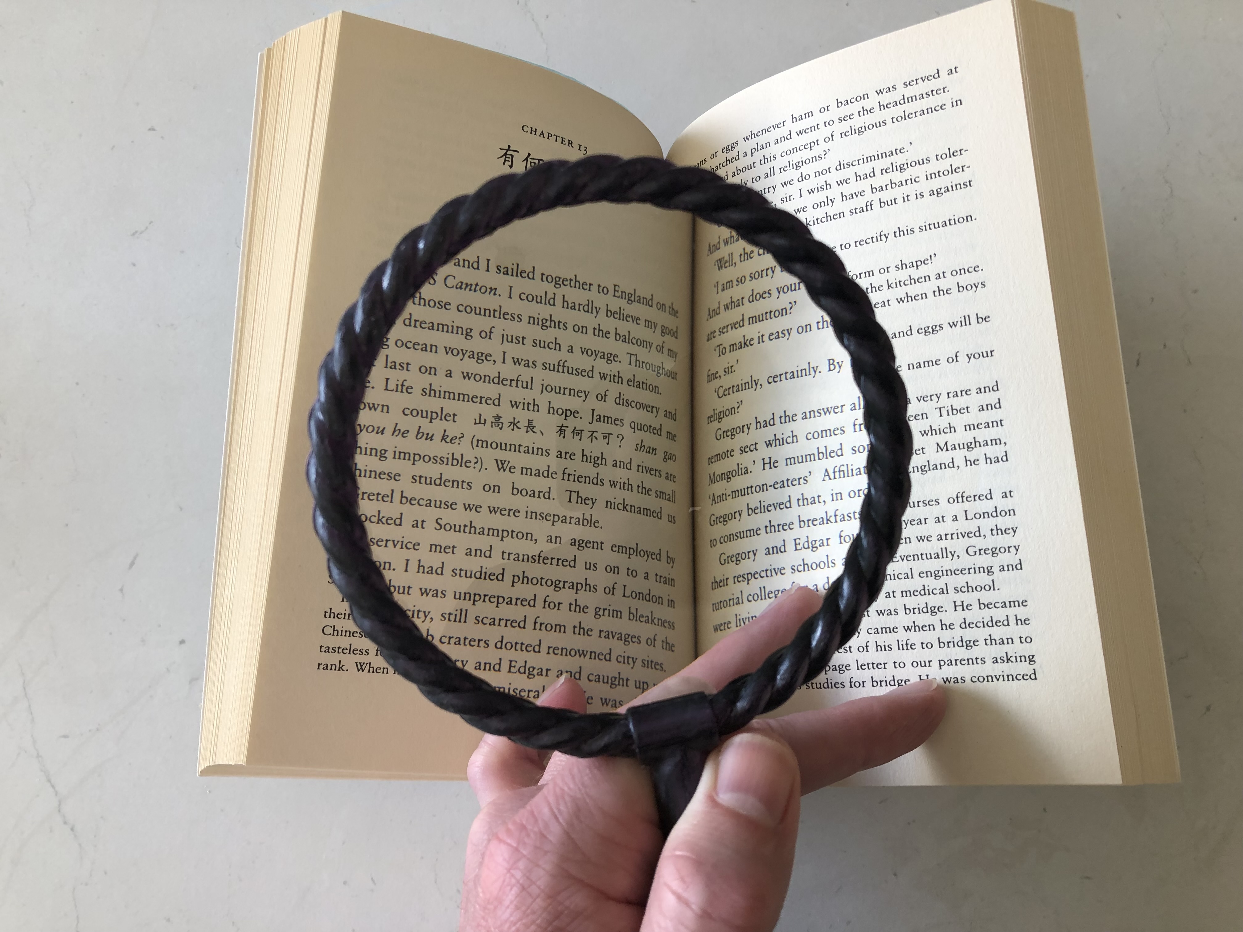
A photo showing the size of the magnifying glass in use. This particular magnifying glass lens was relatively large and powerful, so I was keen to make use of it.
Design idea
The concept I had in mind was to create something that rope that wrapped around the circumference of the lens. I didn’t know how I could model that in OpenSCAD, so it should be a fun challenge, which I believed should be achievable with the appropriate upskilling.
A simple stretch of rope
My first approach was to put three circles together to create a rope cross-section, then linear extrude with a twist to create a straight section of rope. I thought at the time this could be useful as a handle, though I later rejected the idea as being too ropey and straight.
$fn = 12;
rope_diam = 6;
rope_strand_eccentricity = 0.3; // prop. of diam. it should move from center

module rope_crosssection() {
    offset(r=-0.2) offset(r=0.2)
        for(i = [0: 120: 360]) {
            rotate([0,0,i]) translate([rope_diam * rope_strand_eccentricity,0,0]) circle(d=rope_diam);
        }
}

module stranded_handle() {
    rope_length = 100;
    rope_twist_per_unit = 360 / 28;  // one twist per 100 units of length
    linear_extrude(height=100, twist=rope_length * rope_twist_per_unit)
        rope_crosssection();
}
!stranded_handle();
Here’s what that produced. Not so hard, but the problem becomes more significant when we consider replacing linear_extrude with rotate_extrude because you lose the ability to twist it at the same time.

A straight section of twisted rope made from linear extrusion of a cross-section with a twist.
Becoming unstranded to use hull
Doing some research, it looked like similar designs could be accomplished with stacking hulls. I did (very briefly) look at using surface to calculate meshes, but that got complicated much too quickly.
But the problem with using stacked hulls is that the rope cross-section has concave areas, which get lost when using the convex hull operation. So I moved to modelling each strand individually.
When you remember that the cross-section of each strand is essentially a circle that orbits (in a vertical plane) at some small distance around a much larger horizontal circle, then it becomes relatively simple with some loops to position a series of such cross-sections. Each strand section is a hull between one cross-section and the next.
The only complicating thing here is that circle is a 2D primitive, and can’t be located in 3D space. But if you extrude (rotate_extrude) it just a little bit first, like a piece a paper, it is a 3D shape with a thinness that can be essentially ignored.
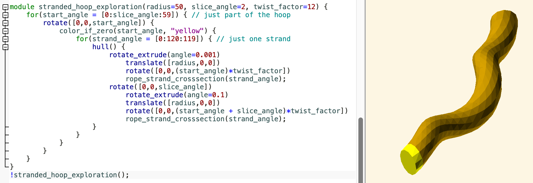
A single strand can be comprised of a series of stacked hulls.
Finishing up the model
From there it doesn’t take much to complete the model:
- Create a simplified stand-in for a lens – a simple cylinder will do – and use that to carve out a shallow (1mm is heaps) recess where the lens will set.
- Add a handle, and something to connect the handle with the lens frame; a cylinder paired with
minkowskiand a small sphere works to give a nice rounded cylinder. - Divide the model in two so I can print it easily, and also allows to insert the lens and super-glue the frame.
- I went a bit overboard adding some locating pins to help the frame glue up well. I just model some small holes that I’ll insert a small (3mm) piece of nail or such. I only needed one on the end of the handle; the lens does the rest.
- Play and tune till you have something you like.
Material selection
I had seen on Temu that you could get small spools of filament: 250g rather than the usual 1kg. Great. I had been recommended to try some multicolour filament, and I thought this would work very well for this project because it has surface normals that are always changing, so you should see the full effect of the two colours interplaying nicely.
Multicolour filament works because when the filament is manufactured, the component colours remain in the same place. So when it comes off the spool and into print-head, when it comes out through the nozzle, the component colour that is closest to the visible side of the perimeter is that gets mostly seen.
I chose a black and dark-purple mix, because I thought that it would have a Chinese laquer sort of look to it, and I think this worked. I still have plenty of the filament left, so hopefully I’ll find something else interesting to make out of it.
The only concern was that the material was PLA, and Silk PLA at that; however this (anonymous) brand of filament performed very nicely with minimal stringing.
Slicing and Printing
I was running out of time to get this finished in the time I allotted, so I sliced this with a 0.2mm layer height and a Speed setting, which is my regular sort of setting. I should have gone for something much finer because the layers were very visible on the top surfaces. I did use 0% infill, as I wanted this to be strong yet elegant. I was still concerned about strength, being PLA… the jury is still out on that one, but it doesn’t seem flimsy at least.
Post-processing
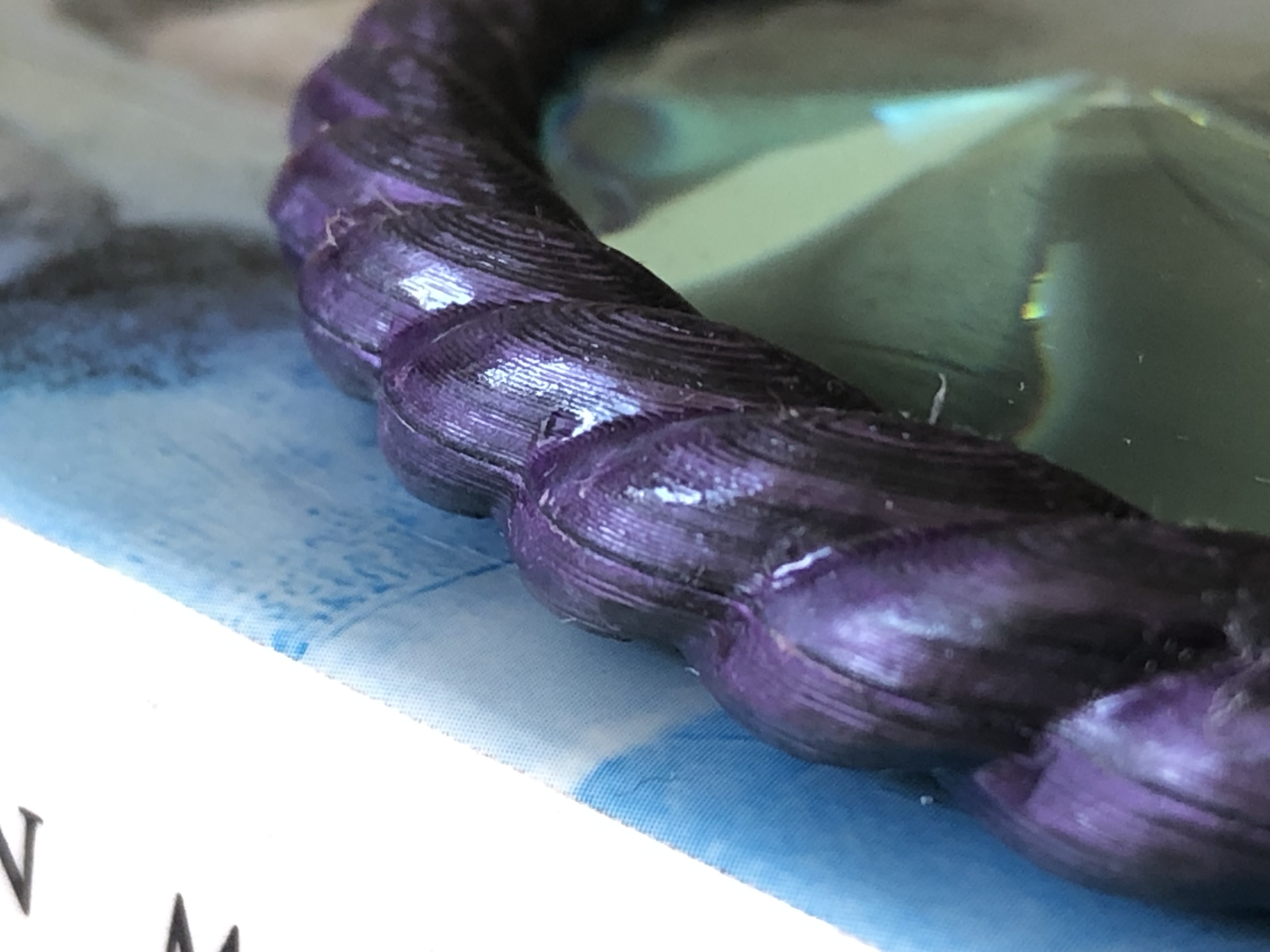
The use of the bi-colour black and purple filament worked well with the modelled rope-strands, showing lots of different angles. I should have used a smaller layer size though, which would have made post-processing easier. What is shown here has been sanded, then coated with multiple layers of experiment.
I should have opted for a smaller layer height… but in the end with some post-processing it did give it some element of wood-grain. Sanding wasn’t as bad as I thought it might be; just working methodically with scraps of 180 grit and then a bit of wet-and-dry sandpaper. I wasn’t going to try for a fine-and-glossy sanded finish; instead I opted to try and layer on a few layers of water-based varnish. I think I started with a matt, then decided it would look better with a gloss.
Having some time ago purchased a flexible neck for my rotary tool, I got some polishing compound and decided to give that a go. I think that was useful, but I probably should have continued with another gloss coat after. If I was doing it again, I would go with a few layers of Mod Podge Hard, which has a nice satin gloss, and then polish that when it was suitably hard. I didn’t give myself that much time though.
Assembly went okay… though I should have had a lot more clamps on hand. I’m not a fan of super-glue, although I did use it.
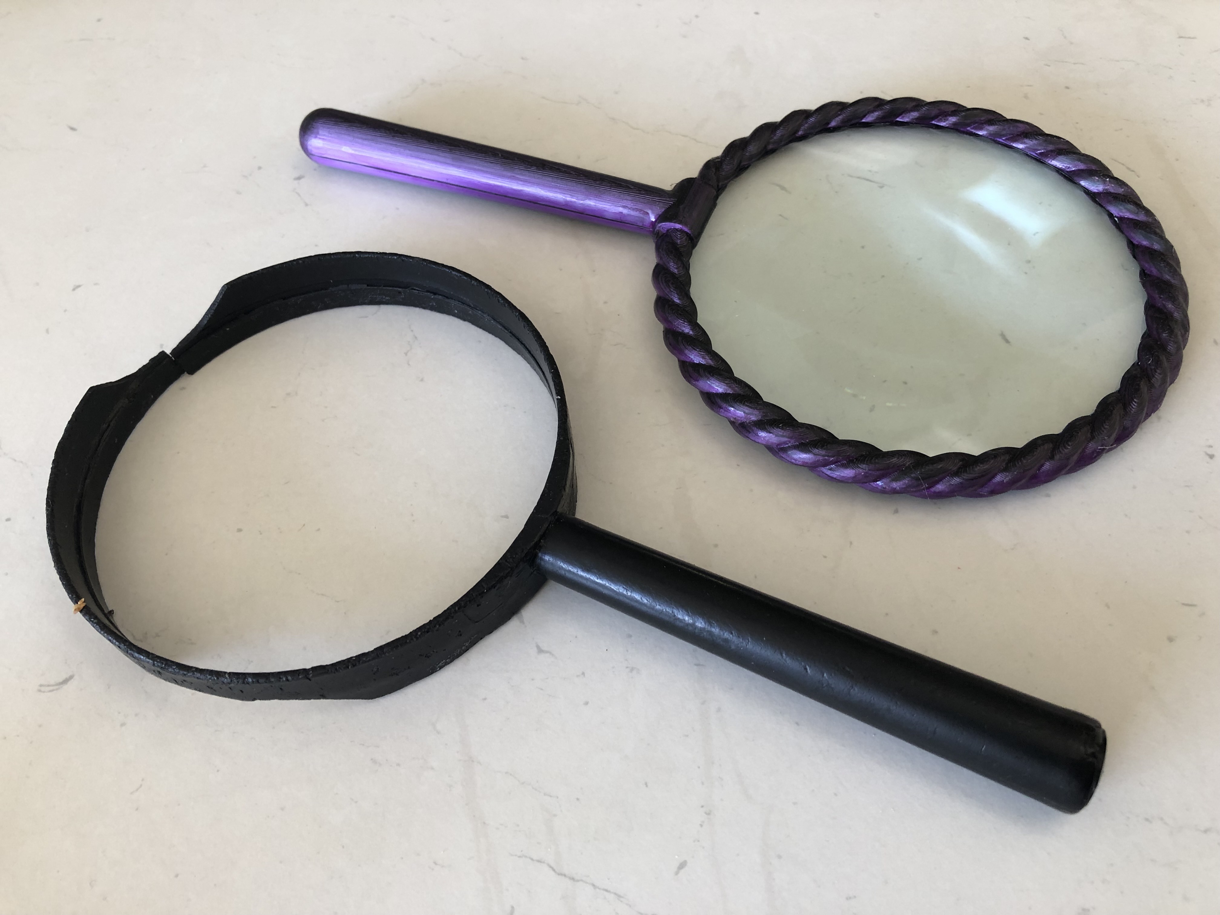
The old and new magnifying glasses together. You can see how broken the old frame had become from being dropped multiple times… but it still had lessons to teach me.
Once assembled, and the glue was dried, I realised an issue: I should have measured the thickest part of the lens. My frame is a little thinner than the thickest part of the lens, so that when you place it down on the table, it will rock on its lens. This is why the original frame is as wide as it is. I think I would also make the handle more grippy, perhaps adding a pommel at the bottom of the handle.
Mum was delighted though, so job done.